6F controller stopped working
6F controller stopped working
Just sent Vlad about this issue, but maybe it's useful to somebody in the public domain too. The controller stopped working when I was riding and pulling ~250W out of it, so no high load. It never has seen high loads anyway cause it's a low-power 250W motor. It's connected to a sensorless 250W motor and 72V (20S) battery. Between ignition wires I can measure the battery voltage. On motor wires there is constantly the battery voltage. Throttle voltage range goes 0.8V - 3.5V, so seems to work as well, as well as the 5V output(s). Motor works fine with other controller.
If needed I can replace parts on the PCB myself, but I have no in-depth knowledge about these circuits or MCU behavior. For example the LVC, how does it work? When it triggers do I need to apply a certain voltage to have the controller operate again? I've also been using the controller with a 36V battery without issues (my BMS has low-voltage protection), so I wonder if LVC is enabled at all.
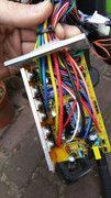
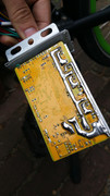
The controller has never seen any rain and all (solder) connections look fine on the PCB.
If needed I can replace parts on the PCB myself, but I have no in-depth knowledge about these circuits or MCU behavior. For example the LVC, how does it work? When it triggers do I need to apply a certain voltage to have the controller operate again? I've also been using the controller with a 36V battery without issues (my BMS has low-voltage protection), so I wonder if LVC is enabled at all.
The controller has never seen any rain and all (solder) connections look fine on the PCB.
Re: 6F controller stopped working
Disconnect the controller completely and check for continuity between each phase and positive/negative power connection. There should be no short anywhere. If there is one, the controller can be repaired by replacing the bad mosfet (a shorted one).
pr0ton wrote: ↑Mon Mar 30, 2020 4:18 amJust sent Vlad about this issue, but maybe it's useful to somebody in the public domain too. The controller stopped working when I was riding and pulling ~250W out of it, so no high load. It never has seen high loads anyway cause it's a low-power 250W motor. It's connected to a sensorless 250W motor and 72V (20S) battery. Between ignition wires I can measure the battery voltage. On motor wires there is constantly the battery voltage. Throttle voltage range goes 0.8V - 3.5V, so seems to work as well, as well as the 5V output(s). Motor works fine with other controller.
If needed I can replace parts on the PCB myself, but I have no in-depth knowledge about these circuits or MCU behavior. For example the LVC, how does it work? When it triggers do I need to apply a certain voltage to have the controller operate again? I've also been using the controller with a 36V battery without issues (my BMS has low-voltage protection), so I wonder if LVC is enabled at all.
The controller has never seen any rain and all (solder) connections look fine on the PCB.