NextGen 24F Quick Start
Click on each item below to show or hide instructions for a specific step.
Step 1. Install +Find a good place for the controller on your vehicle frame and secure it. The best place for the controller is where it receives a lot of airflow as the vehicle is moving and away from heat sources, such as direct sun or the battery
Motor phases. Connect the three heavy-duty wires from the motor (normally colored yellow, green, and blue) with the phase wires on the controller (marked on the cover as Phase: “1”, “2”, “3”). Make sure the connections are secure and there is a good electric contact between lug or bullet connectors. Use non-conductive (such as heatshrink tubes) to ensure electric isolation among all three phase connections as needed.
Hall sensors. Connect the motor 6 pin hall/temperature sensor wires to the controller matching connector located close to where the phases are. The motor side hall connection has the following typical color scheme: Red – 5v, Black – Ground, Green, Blue, Yellow – hall signal 1/2/3 (order is not important), White (temperature sensor). Refer to the controller Signal Connector Pinouts section below to match the hall connections.
Battery. Before connecting the controller to the battery, we highly recommend installing a properly rated for your battery DC breaker such as one used in solar applications or similar designed specifically for DC (as opposed to AC). While keeping the DC breaker in the OFF position, please connect the positive and negative wires from the controller marked correspondingly as “+”and “-” to the battery. Ensure good electric isolation between the battery positive and negative connections.
ON/OFF. Connect the two wire on/off connector on the controller to a key switch.
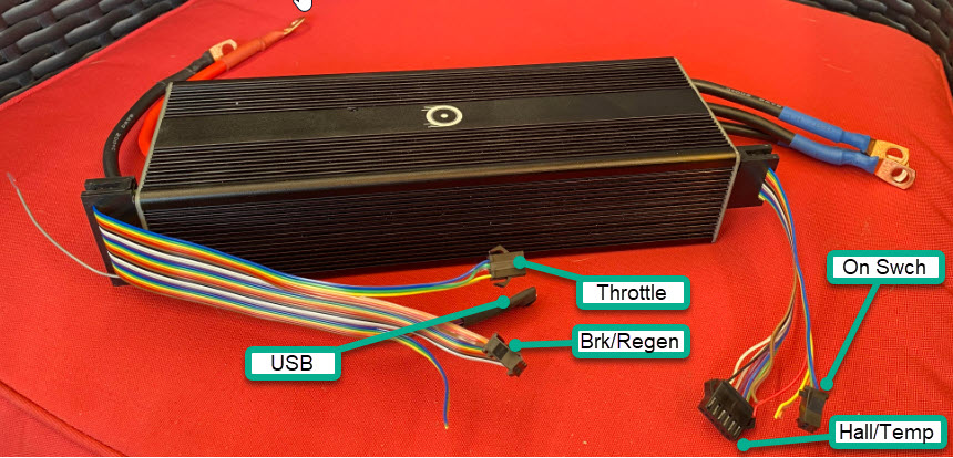
Controls. On the opposite side of of the controller, connect the accelerator throttle connector (marked as “Thr“) and a regenerative brake throttle connector (marked as “Brk“) each to their respective throttles installed on your vehicle. Resistive or hall based, including twist or thumb throttles can be used on either of these connections. Refer to the controller Signal Connector Pinouts section below to match the throttle connections.
Other wires on this side of the controller are reserved for future use.
Power up your controller first by setting the battery circuit breaker to ON position and then turning the key switch. If the controller is properly connected, it will sound too long confirmation beeps.
All NextGen controllers have WiFi capability that allows receiving over-the-air firmware updates.
Once your controller is on, use your phone to scan for new WiFi connections and find the controller advertised name appearing as PVConfigMe-XXXX where XXXX is a unique identifier for your controller. Please make a note of four letters and/or numbers. Select PVConfigMe-XXXX from the list and enter the password for connection which should look as combination the word “nextgen” and your controller unique identifier (XXXX). For example, if your controller identifier is A7B9, the password that you need to enter is nextgenA7B9. Once you connected successfully, you will be offered to connect your controller to the your wireless network. Please select your wireless network name and enter its password. Also, please ensure to enter your valid email address in the corresponding field. If the connection is successful, you will hear three short ascending-pitch beeps from the controller.
The easiest way to configure your controller for your specific motor and the battery is by using the phone application (iOS or Android). Please install the application for your phone by scanning a barcode on the side of your controller or selecting your platform below from your phone:


Once installed, open the app, click on the menu button in the upper left corner and select “Setting”, then “Connect”. If the controller is on, you will see the controller name such as “PV24F-xxxx”. Select the controller name. You will be prompted to create an account and then enter the selected login name and password. This needs to be done only once. From this point, the dashboard screen will be receiving telemetry data and you will be ready to detect your motor and finish the controller configuration.
Safety Warning! Detection procedure involves spinning the motor, therefore, please ensure that the wheel and/or the motor is raised off the ground and otherwise free from obstruction. Be aware that the motor may spin in reverse direction, therefore, make sure that anything connected to it via chain such as pedals can spin freely in any direction and there is nothing in the way.
In the phone app, tap the menu button in the upper left corner and select “Program” -> “Motor”. Ensure the motor and/or wheel can freely spin, do not change any settings just yet. Select “Detect Now” and wait for the motor detection procedure to complete. Review the video below for detailed steps. Note: A computer with the vesc tool is not necessary to perform motor detection or other configuration steps. The phone app is enough to complete all the necessary configurations.
Video. Motor detection
Once the motor is detected successfully, enter the “Throttle” menu to configure your accelerator and brake throttles. Once on the Accelerator screen, twist the throttle from 0% to 100% for the controller to detect the upper and lower throttle voltage limits. If the throttle is connected correctly, you should observe the indicator bar to respond and Max and Mid Voltage to change as you twist the throttle. Repeat the procedure with the brake throttle if you have one connected. If If you have both the accelerator and the brake throttles connected, from the “Type” drop-down menu, select “Current No Reverse Brake ADC2”. If you only have accelerator throttle, select “Current”. After trimming the throttles and selecting the control type, tap on the “Update” button to save the throttle configuration.
Once you get to this step, your motor should now be able to respond to the accelerator and brake throttles. Test with the wheel raised and unloaded to ensure you are getting smooth rotation as you apply accelerator throttle and smooth brake as you apply the brake throttle if connected.
Motor detection completed in Step 6 sets conservative parameters for the motor power output to make sure you can safely test it before raising the power limits. If the tests in the previous step have been successful, you may want to adjust the current settings in the “Power Limits” section of the “Program” menu of the app to match your battery and motor ratings and your power requirements. Remember to never exceed the actual charge and discharge ratings of your battery or motor power limits.
Notice the orientation of the interface connectors (very important): Wires are facing outward from the phase and battery connections!
Wire colors have no significance but the order does.
Battery connection side pinouts (larger interface connector on the left of the picture), counting from the top to the bottom of the controller:
Throttle Brake/Regen USB/Programming with PC VESC tool
1 – Thr Signal 4 – Brk Signal
2 – GND (Isolated) 5 – GND (Isolated)
3 – 5v (isolated) 6 – 5v (Isolated)
Motor phase connection side pinouts (smaller interface connector to the right on the picture), top to bottom:
On/Off Hall/Motor temp
1 – Batt Input 7 – 5v_nonISO (Non-isolated)
2 – Batt Positive (Careful!) 8 – Motor temp signal
– 9 – Hall 1
– 10 – Hall 2
– 11 – Hall 3
– 12 – GND_PWR (non-isolated, same as battery negative)
Additional connectors (CANBUS, Servo/Cruise, etc to be added).
Important!
The GND and 5v on the larger connector interface are NOT the same as GND_PWR and 5v Non-ISO on the smaller connector.
They must NOT be connected together or mixed anywhere in the vehicle wiring.
GND and 5v on the larger interface connector are isolated from the battery positive and negative inputs to provide the best signal integrity and safety. No pins on this connector should be used to power any accessories.
Mixing isolated and non-isolated connections will cause improper operation and can lead to damage of the controller!