Brake Subsystem
The brake subsystem on PowerVelocity controllers is managed via three connectors, conveniently named EBS-, EBS-, and EBS+. Having so many connectors might seem confusing at first, but the reason is because they offer you multiple ways to wire your bike’s brakes up to the controller, depending on your particular use-case. At a high level, we suggest you first decide on whether to use a “negative” approach vs. a “positive” approach. Each has its pluses and minuses (pun intended).
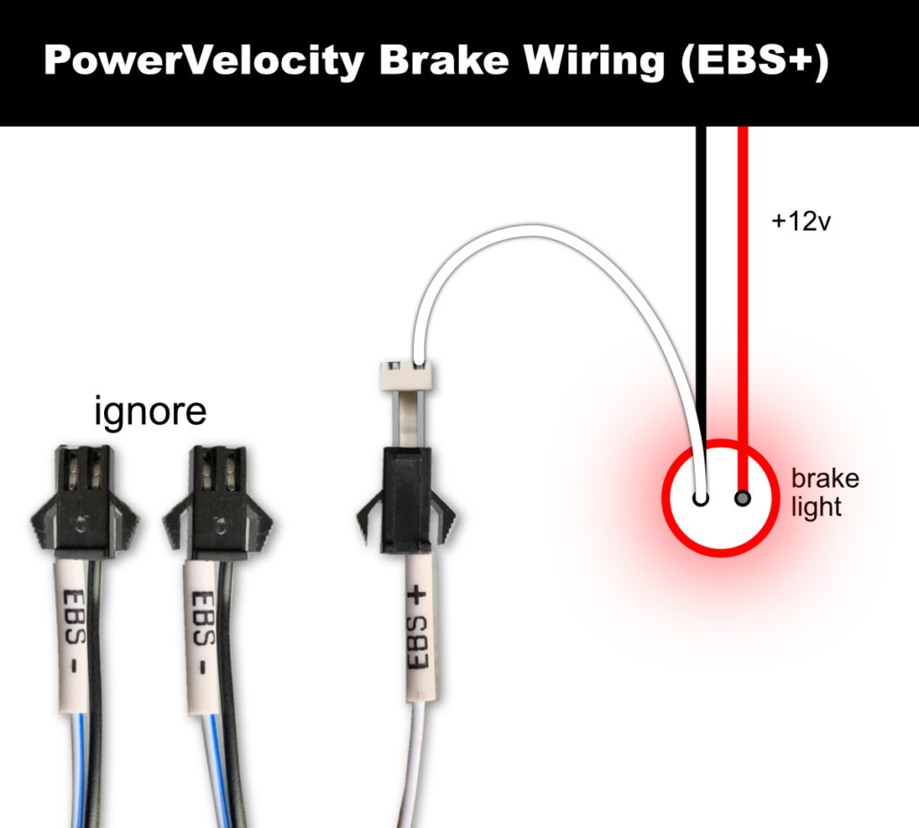
If we chose a “positive” approach, we will only be using the single EBS+ connector and will ignore the dual EBS- connectors (i.e. they will not be used at all). The single EBS+ connector is expecting a 12VDC NO (Normally Opened) switched circuit and assumes you are using a non-isolated, common ground between the high-voltage battery pack and the 12VDC subsystem. Note: If your bike uses an isolated DC-DC converter, then this approach will not work. Instead you must use a “negative” approach as described below. An example of such a circuit on your bike might be the rear brake light — whenever it lights up there will be 12VDC available. Simply tapping into the bike’s 12VDC brake light circuit is usually the easiest way to wire up the EBS+ connector. While this is the simplest solution, one downside to this approach is that the Bluetooth adapter will not “know” when the brakes are applied, thus certain functionality will not be available to the PowerVelocity App.
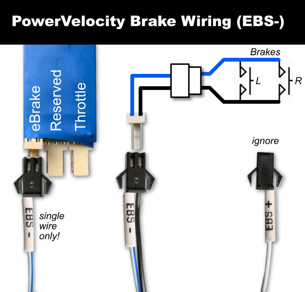
If we chose a “negative” approach, there are multiple options available to us. Note: The EBS- connectors are expecting no more than 5VDC — sending 12VDC through this connector is a sure way to destroy the controller’s MPU! The simplest “negative” approach is to use a NO shorting switch to complete the 5V circuit using either one of the two EBS- connectors. So then, what is the other unused EBS- connector for? Simple: you hook that up to the Bluetooth adapter as shown in the diagram (Be sure to only use a single wire as shown). In this way, the Bluetooth adapter, and thus the PowerVelocity App, will now be aware of when the brakes are applied.
Another alternate “negative” approach is to isolate the 12VC from the 5VDC using a relay. One such approach is shown below — with the caveat being that this approach assumes you use a low-wattage relay (e.g. < 2W) so as to not adversely affect the brightness of the brake light itself.
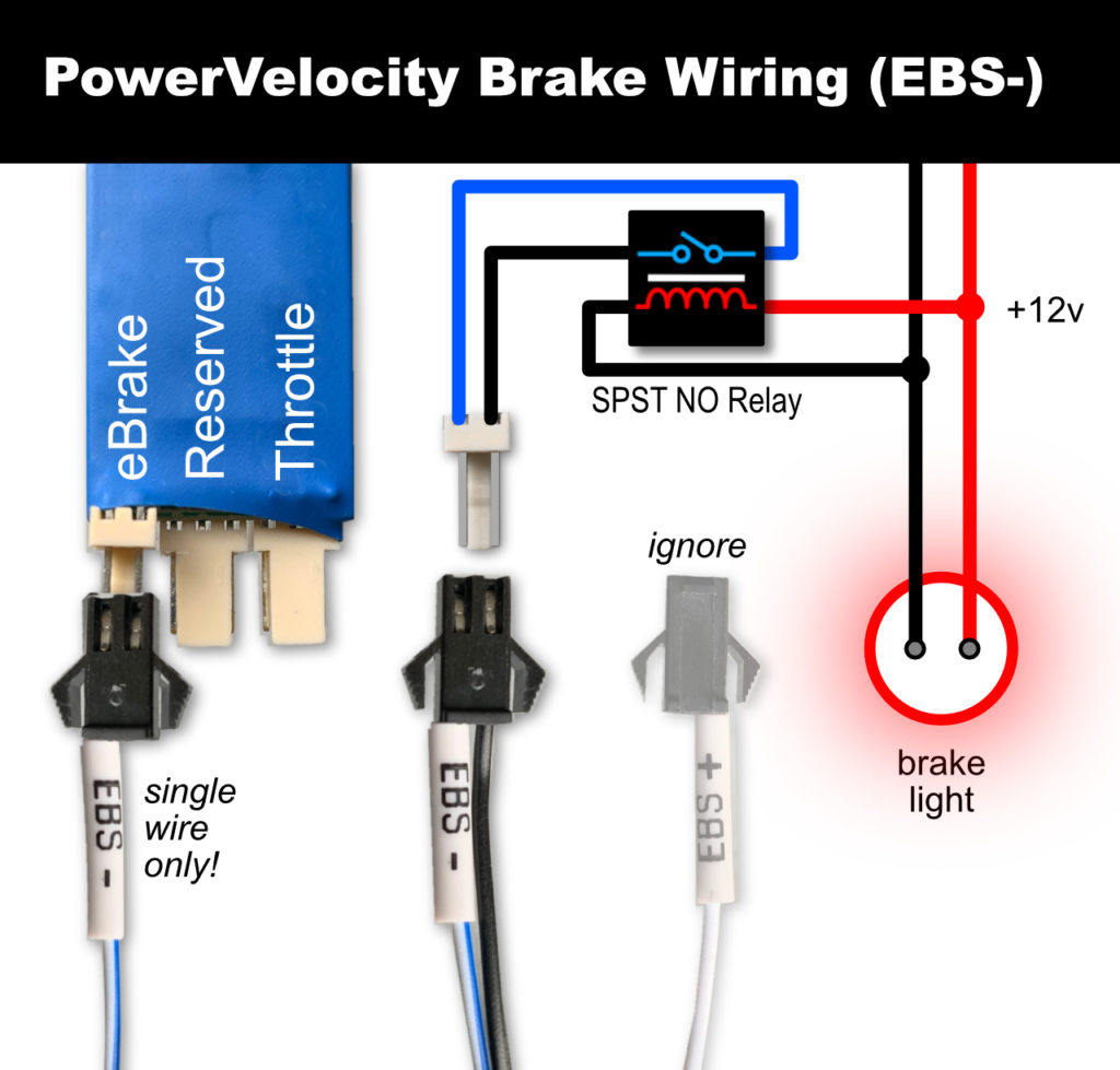
Note: it is critical that no 12V ever “bleed through” the relay to the EBS- circuit! If you want to be especially vigilant, wiring up an Opto-relay should do the trick.